
UPDATE Jan 2022: Having played with the prototype for a while it’s apparent that the overall gain in the filtered (wet) output circuit is not sufficient for modular (by at least 24dB!). The Q/Bandwidth control is also not as responsive as I’d like. I will keep the same topolgy for the filter (to save a re-spin) but make some simulations and adjust some resistors to improve the gain staging in due course.
Last year I bought up a copy of Nicholas Collins’ recently updated ‘Handmade Electronic Music’. It’s full of interesting ideas and jumping off points and one chapter that caught my attention described a low parts count FM receiver using the SDR Rx-on-a-chip the Si4825. I use the MusicThing ‘Radio Music’ a lot for sample playback and random ‘radio’ snippets but I like the idea of sequencing and sampling live radio. I also want to generate interesting noise with the potential for ghostly broadcasts as a percussion source, and just have a simple way of listening to Radio Skye through decent speakers!
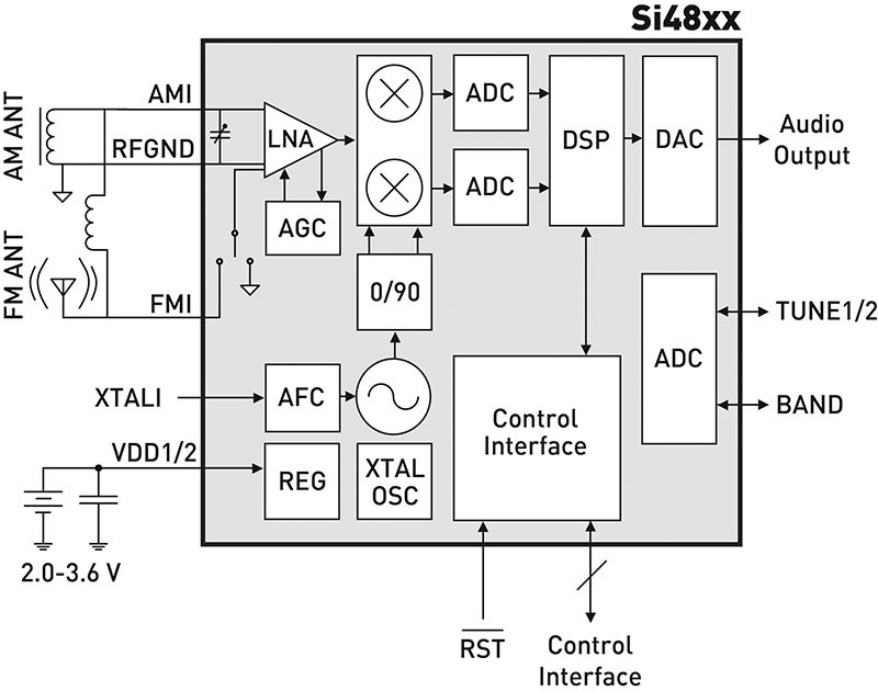
Silicone Labs make a number of these DSP Rx ics but the Si4825 is one of the few available in 2020 with mechanically controlled tuning making it suitable for voltage control. FM, AM and multiple SW bands can be selected using a rotary switch and specific resistors. No SSB which would have been fun although it’s possible the same die could be ‘enabled’ to allow this according to some HAM forum chat but I couldn’t find any more info on this. They are also cheap (~£2 from Mouser at time of writing) and there are three good documents to help with the design: the datasheet; antenna design guide and the demo board user guide (links at the bottom).
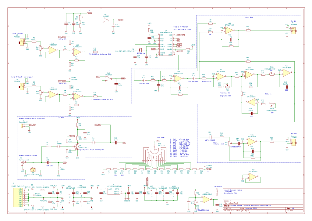
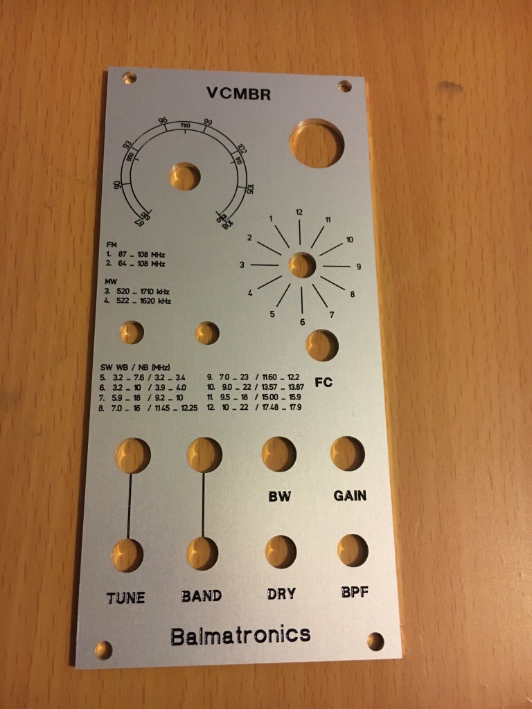
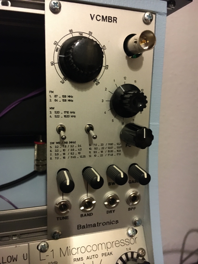
I decided to fit it for 12 bands, similar to the design guide example (but with European/UK FM bands) although some of the SW bands are similar. The core of the circuit is faithful to the standard datasheet etc. examples. The antenna signal processing is also derived from the datasheet and associated docs. CV input processing stages were added to attenuate and buffer the CV inputs (for tune and band) and the audio output is amplified to modularish levels. An auxiliary output was added featuring a State Variable bandpass filter with adjustable fc, gain and BW as a means of shaping the noise when used as a percussion noise source.
CV Processing
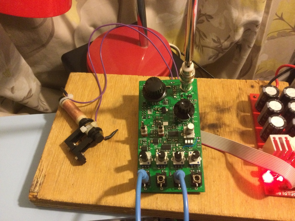
I decided to jump straight to KiCAD for prototyping the circuit, having used well-known (datasheet/textbook) circuits and simulating what I could (BPF and CV processing) in LtSpice prior to laying out the circuit to verify refine the values. One drawback of this is that I wasn’t sure exactly what voltage Tune1 and Tune2 were or how they interacted. The Si4825 runs from 3V3 and the Tune inputs shouldn’t be driven above this or below 0V, so the CV opamps are 3V3 single supply and to accomodate worst case +10V CV signals, 20dB attenuation is applied to the CV input, then the input is biased to an adjustable reference voltage (I guessed 3V3/2 but turns out to be 0V5 to centre the CV). The CV processing could be improved by normalising the Tune pot to the Tune CV input and bypassing the relevant switches. The Band Select CV real-estate would be better used either as an additional Tune CV input; CV input or external input for the BPF.
Output Amplifier and Bandpass Filter
Two outputs are available – dry and bandpass filtered. The filter has manually adjustable Fc and bandwidth and an adjustable gain stage follows. The purpose of the filtered output is to help shape noise for use as a percussion source and additional gain if required – for small signal audio, modulars run quite hot!
Draws: 50mA on the +12V rails; 30mA on the -12V rail
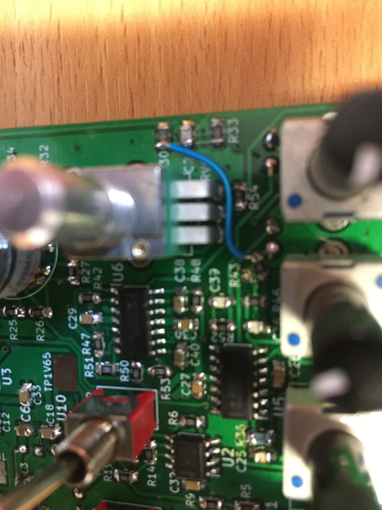
V0.1 PCB Kludges
R50 needs to go to the other side of R42.
Q pot to 100k for better BW resolution on the BPF output
R36 optionally lowered to 10k for normalised dry/wet levels
R43 should connect to R30/R33 C24 for better isolation from wet output
Possible Improvements for Mk2
- The band select CV is a bit pointless – board space and hardware would be better used either as CV control for filter or additional Tune CV input, or perhaps an auxiliary filter input for more complex percussion sounds.
- The Tune CV processing should be redesigned and simplified knowing now how the Tune2 works and the voltage it is at. This would remove necessity for the CV source switches (although toggling these can be fun!), the reference voltage and buffer and probably one of the CV input opamp stages. The manual Tune control could be normalled to the Tune CV input
- The Position of the band select switch should be moved further North, and orientation of switch would be better 180deg
- Fewer SW bands would allow more/cheaper switch options.
- SW wide/narrow switch, fitted for but not with?
- Fix layout errors – R43 and R50 routing.
- The Si4825 is the least ‘smart’ (and cheapest) of SIs broadcast radio Rx SoCs – fine for use as a musical sound source but for more serious recievers, other Si chips such as Si4844 offer features such as I2C interface, valid station indicator, stereo output, RSSI etc.
- Panel – move FC pot down a bit and better ‘calibrate’ the tune pot dial print!
Links
https://www.nutsvolts.com/magazine/article/june2013_OpenCommunication

can you make one for me? would love a eurorack cv controlled radio
LikeLike
Hi Jed, I think if I were to make these to sell I would revise the pcb as described (ditch the switches, fewer band selections, revise the panel etc) to improve the functionality and reduce the bom cost. At some stage I’ll upload the gerbers and panel files if anyone wants to build their own. I do have a couple of spare pcbs (no panels) of the prototype i can post for shipping cost only if interested but it’s surface mount, 0805 with some kludges required so probably an intermediate level project. There are a few commercial ones out there like the rf nomad (sw only i think?) or if your up for a bit of diy the Nicolas Collins book walks theough building a simplified FM only version
LikeLike
Hello, i really want tp build this. For a few years i thought to build something around si4824 ( nowdays absoulete). Care to share sch or gerber files? Can i buy a pcb + panrl from you?
LikeLike
hello, for the past 4-5 years i thought about trying something like this, originally i had in mind the si4824 (obsolete now days). this is a great read, you might inspired me enough to install kicad and try something like this 🙂
care to add information? schematics? gerber file? can i order a pcb from you?
LikeLiked by 1 person
Hi,
I want to build a CV controlled Eurorack Radio Module for a friend who is into Modular Music. I’m a electrician in training for Micro electronics and this would be a nice project for practices. Would share your Gerber file or sent me a pcb ?
Best regards !
LikeLike
Hey Campbell, I have a Sangean MMR-77 with the Si4836 IC. I’d like to see if I can add the SW features and hoping I can toss a few ideas back and forth with you. Thanks.
Greg
LikeLike
Hi Greg, happy to help if i can – i haven’t looked at this for a few years so a bit rusty!
LikeLike